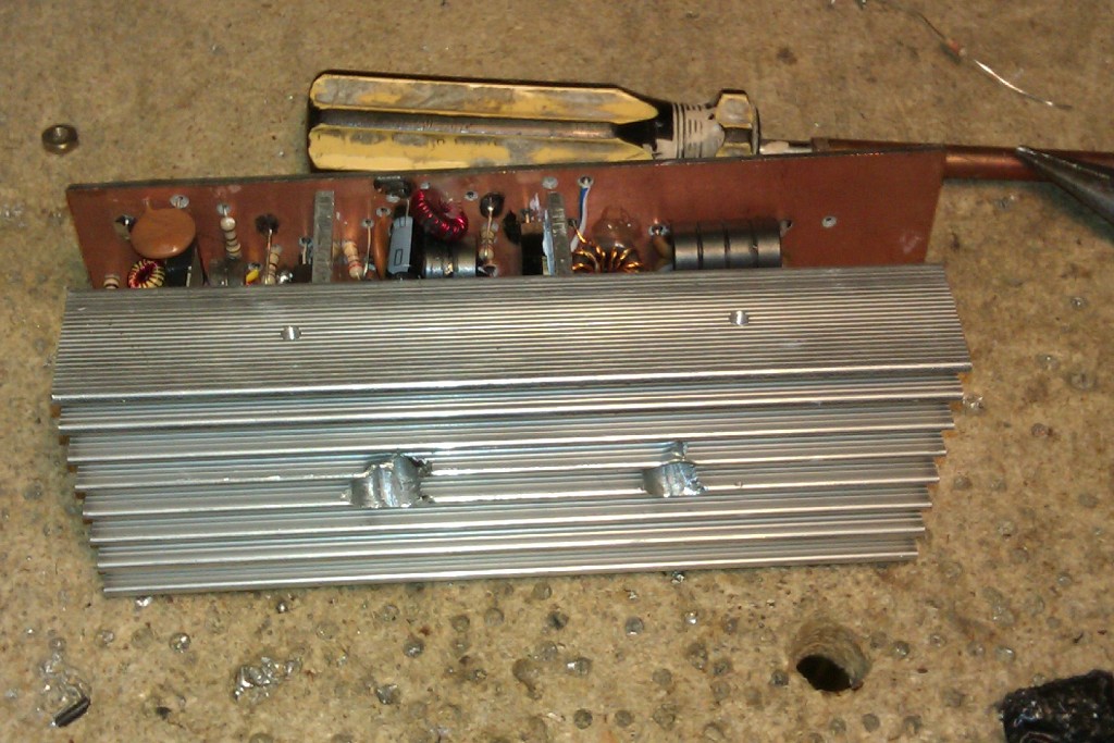
This transistor HF 20W linear is used in a all band HF transceiver due to be shown elsewhere on this site, it is shown here as it may be useful to others as a simple low power HF pa for various projects. Although the current trend is MosFets for linears now, bipolar transistors are still cheaper than FETS ( you can buy four 2SC1969's for £10.00 on Ebay, these are not original Mitsubishi devices but are made by Eleflow and are equally as good as the obsolete Mitsubishi transistors, a single RD16HHF1 HF FET however costs around £4.50. Four 2SC2078 drivers are also available for £8.50 at the time of writing )
For approximately 50mW - 100mW input the linear will produce 15 - 20 Watts output depending on the band. The transistors used are primarily designed for CB use and as such exhibit a greater gain at LF compared to 27MHz so a gain compensation network is included at the input of the amplifier to ensure a reasonably flat frequency response across the HF band ( 1.8MHz - 30MHz ), this can be omitted if you whish. The 130pF and200pF capacitors across the primary of the driver/ output transformer peaks the HF response above 10MHz also ensuring a flat response.
All of the transmission line transformers are made from stacked ferrite cores. Two part Epoxy glue is used to hold the torroid cores together. Simple temperature compensated bias networks are used for the driver and final transistors, these consist of a 1N4001 diode thermally coupled to the transistor pairs ( see photographs ). The driver pair of transistors run with a quiescent current of 15mA each, the output pair are 30mA each. Ideally matched pairs of driver and output transistors should be used, the devices I used were all from the same batch and were within 20% of each other. You can check the forward Vbe using the diode function on a DMM and also the Hfe of the devices to ensure a reasonable match - the Hfe is the most important matching factor. The 220R variable resistors shown in the circuit diagram are used to set the standing current of the transistors, fixed resistors were used here as no presets were available.
At full power output current demand is approximately 2.6 Amps. Both pairs of transistors should be adequately heatsinked. Here, some aluminium angle was used to mount the transistors, this is then bolted to the main heatsink - be sure to use some heatsink compound on the transistors and the juction between the angle / main heatsink. The heatsink was salvaged from a scrap UPS. Double sided fibre glass copper clad board was used to make a PCB, single sided would also be fine but none was to hand.
Barry Zarucki M0DGQ
HOME